
Technology
Function
Function
 Between non-lubricated bearing planes the solid lubricant has a smoothing effect ( yield smoothing ); it fills the roughness deepenings and covers them with a thin, hard, durable and continuously renewing lubricating film.
At a recommended surface quality of the shaft (steel) with a roughness dept of Ra ≤ 0,8 and a plain bearing bore hole (bronze) of Ra ≤ 1,2 the micro-roughness which are necessary for the tool life of the lubricating film are formed.
In the starting phase the inlet film, which is applied by the company, prevents the peaks on the surfaces from squeezing against each other or from interfering into the cavities of the mating material.
The micro abrasion caused by the operation of the bearings (load and slip velocity) is pressed into the solid lubricant depots with the effect that the lubricant which was released by displacement fills the micro roughnesses.
The emerging solid lubricant film divides the two slip partners permanently and with a low frictional value, a minimum abrasion and a long life.
Even under high static loads the frictional coefficient is strongly reduced when starting which avoids dry running as well as welding (corrosion).


Solid lubricants
Solid lubricants
Solid lubricants consist of smallest lamella-like parts which slightly shift against each other and which are able to effectively separate metallic sliding surfaces from each other owing to their coating grid structure.
The bindings of these crystal structures are strong within the layers but substantially weaker between the layers.
Thus, these substances are easy to shift in the direction of the layers and can therefore take very high loads vertically to the layers. The good sliding effect and the high load capacity of the solid lubricants results from this.

The slip motion causes the solid lubricant lamellas to embed themselves into the surface roughnesses of the sliding materials where they form a dry lubricating film trough developing layers so that the sliding surfaces do not get into contact with each other.
The solid lubricant lamellas which are unsorted in the lubricating slit are straightened and pressed together parallel to the surface by forces affecting them from the vertical. Resulting from this a closed solid lubricant layer is formed which, due to its compressibility, partly absorbs any influencing pressure and spreads it on a bigger surface.

Parallel and accordingly high back pressures create a damping effect in the lubricating slit. The interaction prevents a hardening of the upper metal layers as well as a formation of hardening, deformity or bending zones, the so-called Clod build-up which occurs in zones close to the edge of the plain bearing.

Application area
Solid lubricants are used where a hydrodynamic lubrication cannot be achieved. Furthermore they are also used where conventional lubricating films would not withstand pulsating loads.
The combinational solid lubricants developed by SL Gleitlagertechnik meet these high demands in every respect.
In addition to 99,9% pure, chemically neutral, noncorroding graphite, standard anorganic lubricants like molybdenum disulphide (MoS2), tungsten disulphide (WS2), polytetrafluorethylene (PTFE) are used, as well.
The optimal effectivity of the lubricant is achieved by the combination of the components and their advantageous properties with the covering of the solid lubricant in the slip direction, which allow an equal distribution of the lubricant.
working temperature in air:
- graphit (99,9%, pure) up to 430°C
- graphit and PTFE up to 250°C
Additionally, special lubricants and special materials are available on request.
Although the plain bearings are self-lubricating and no additional lubricating agents are required, all solid lubricants can be used in combination with other lubricating agents ( oil, grease, etc. ) or lubricating systems as far as these do not contain any other solid lubricants or substances with abrasive properties.
In order to make sure that in such case no disadvantages arise due to interaction of the lubricants on each other, it is recommended to point this out by the inquiry.
Solid lubricants with crystalline flake structure
| properties | graphite (99,9% pure) | molybdenum disulphide | tungsten disulphide | polytetrafluorethylene |
| C | MoS2 | WS2 | PTFE | |
| working temperature (° C) | − 120…600 | − 100…400 | − 180…600 | − 200…260 |
| frictional coefficient (μ) | 0,1+…0,18 | 0,04…0,09 | 0,08…0,18 | 0,04…0,09 |
| applicability in air | very good / good | very good | very good | good |
| –water | very good | – | good | good |
| –vacuum | not so good | good | very good | very good |
| resistance against | ||||
| –(sea) water | very good | not so good | not so goot | good |
| –chemical | very good | good | good | good |
| –radiation | very good / good | – | good | good |
| crystalline structure | hexagonal | hexagonal | hexagonal | – |
| colour | greyish black | greyish black | greyish black | transp. / white |
| oxidations–/ decomposition product | CO, CO2 | MoO3, SO2 | WO3, SO2 | C2F4 |
+) The frictional coefficient of pure grpahite could decrease in water (also sea water), other liquids, humid air, steam or under other ideal tribological conditions down to a value of 0,03.
Selection Criteria
Selection Criteria
Load
The surface pressure p (N/mm²) of the sliding surface should not exceed the permissible pressure (see figure: capacity diagram).
 p = 1,5 ⋅ F/A (parabolic)
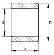
A = d ⋅ b
with:
F (N) = bearing load
d (mm) = Ø bearing bore hole
b (mm) = bearing length
A (mm²) = bearing surface
The allowed surface pressure is determined by the bearing material and the existing lubricant which should remain functional under load.
The allowed maximum load is 150N/mm².
Sliding velocity
Under load the maximum sliding velocity v should not exceed 60m/min.
Bearing Capacity
L= F · v (thermic load capacity)
As modification of this formula the value p·v is used for the calculation of plain bearings.
The p- and v-values indicated in the capacity diagram are threshold values from which the frictional heat is carried out from the plain bearing by heat conduction and emission, in such an extent that no increase of heat in the sliding surface takes place. For special cases the customer should draw up a heat balance on the basis of the whole construction. If necessary solutions for heat dissipation should be considered during construction.
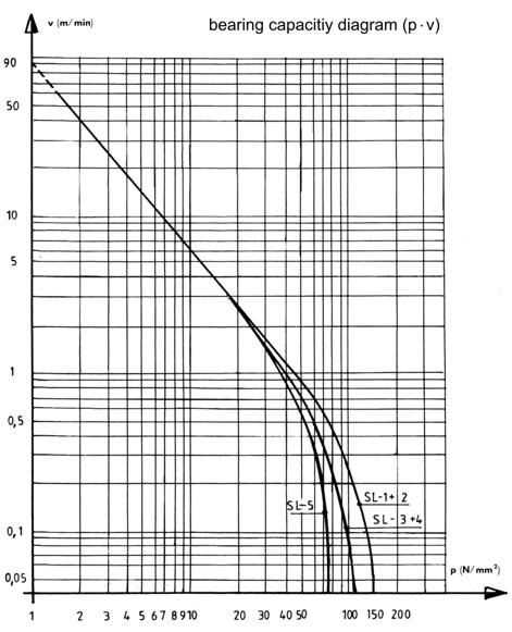
Parameters: frictional distance 500 metres, bearing bore hole Ra ≤ 1,2
mating material: St 1.4057, Ra ≤ 0,8, HB 240
sliding direction: rotating in continuous operation at room temperature
Construction
Construction
SL plain bearings are generally applicable for all sliding motions or motion combinations. Special constructions can be made according to the customers drawings. In this case the arrangement of the dry lubricants will be checked or defined by the company.
The recommended length of the plain bearing is 0,75 x d up to 1,25 x d.
Plain bearings which are too short have an insufficiently fit in the housing which results into a lower load capacity. If the plain bearings are too long, they can only be mounted with difficulty.
In order to avoid edge pressures due to misalignments, the plain bearing bore holes (sliding surface) can be supplied with load relieving chamfers. If the resulting misalignments are to high, which could happen at welded constructions for example, the use of a spherical ball bearing is recommended.
Up to an inside diameter of 500 mm and a temperature up to 80°C the following fits for plain bearings are recommended:
| Version 1. | |||||||
| plain bearing inner diameter: | E7 (decreases down to H9 after pressed-in) |
||||||
| plain bearing outer diameter: | s6 or r6 | ||||||
| shaft: |
|
||||||
| housing: | H7 |
| Version 2. | |
| plain bearing inner diameter: | C7 (decreases down to D8 after pressed-in) |
| plain bearing outer diameter: | s6 or r6 |
| shaft: | h7 |
| housing: | H7 |
Other fits are possible if a safe fit of the plain bearing in the housing is achieved and the required operational bearing clearance in the plain bearing bore hole is given.
| required surface qualities | |
| shaft: | Ra ≥ 0,2 and Ra ≤ 0,8 |
| inside plain bearing: | Ra ≈ 1,2 |
| outside plain bearing: | Ra ≈ 3,2 |
| housing bore hole: | Ra ≈ 3,2 |
Mating material
The mating material should have a minmal surface hardness of bearing material hardness + 100 HB as well as a surface quality between Ra ≥ 0,2 and Ra ≤ 0,8.
Especially for the use in water and liquids corrosion-resistant steel is recommended as a suitable mating material. Protection from corrosion may also be achieved if the shaft is hard chrome plated. Then the required hardness must be at least 800 HV and the layer thickness > 50 μm.
HV = Vickers hardness
HB = Brinell hardness
The shrink fitting of a collet or the welding of stainless steelplate on the shaft with a rework or a salt bath nitriding can be seen as alternatives.
Mounting
Mounting
Because of the given overlap sizes (outer diameter of the plain bearing/ bore hole of bearing housing) the elastic deformation of the bearing is used for building up the fit pressure (prestressing).
The bore hole of the bearing housing must be machined carefully and has to be supplied with an assembly bevel.
Under high temperatures higher overlap sizes may occur which are due to the different thermal expansion coefficients of the materials (plain bearing/ bearing housing).

Here, in order not to exceed the allowed fit pressure in the bearing housing, transition fits are used. In this case a fixing of the bearing has to be ensured
Installation of the bearing
The installation of the bearings can either be effected by force fitting or by subcooling with carbonic acid (CO2).
A specially made arbor press may be supplied by the company (relating to the order) to ease the force fitting and to avoid damages of the plain bearing.
Models